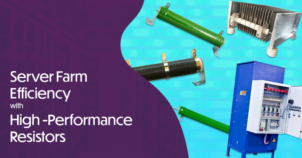
In the rapidly advancing field of technology, the backbone of a successful server farm lies not just in cutting-edge software or the latest in server hardware, but in the critical infrastructure that supports it. Among the components that play an essential role in this infrastructure, resistors take center stage, especially during the initial stages of a server farm build-out. At Hill Tech, we specialize in supplying high-quality wire-wound resistors, grid resistors, and load bank resistors that ensure optimal performance and reliability for server farms around the globe.
Why Resistors are Essential for a Server Farm
- Load Testing: Before a server farm becomes operational, it’s crucial to simulate the electrical load it will experience. Our resistors offer the perfect solution for load testing, allowing data centers to confirm that their power and cooling systems can handle maximum capacity. This preemptive testing helps detect potential weaknesses in the system infrastructure, ensuring everything is ready for smooth operations from day one.
- Thermal Management: During the testing phase, managing heat is as critical as managing the electrical load. Our resistors help stabilize temperatures, preventing possible overheating and ensuring cooling systems are operating effectively. This is vital in maintaining the server farm’s overall health and longevity.
- Infrastructure Evaluation: Using our resistors in the evaluation process of your electrical infrastructure can significantly enhance the reliability of your systems. Before servers go live, our solutions help identify any issues that could impact performance, providing peace of mind that all components will function seamlessly together.
Explore Our Product Offerings
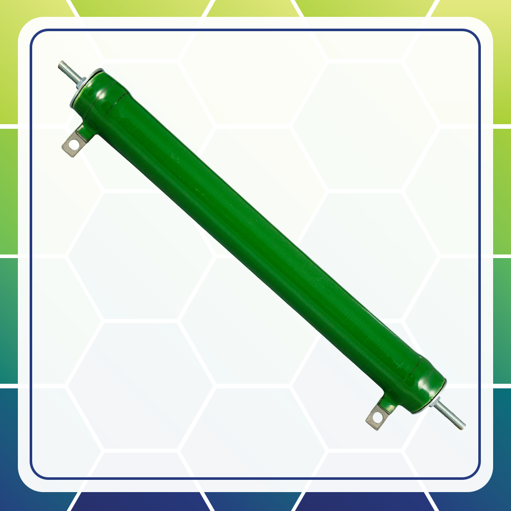
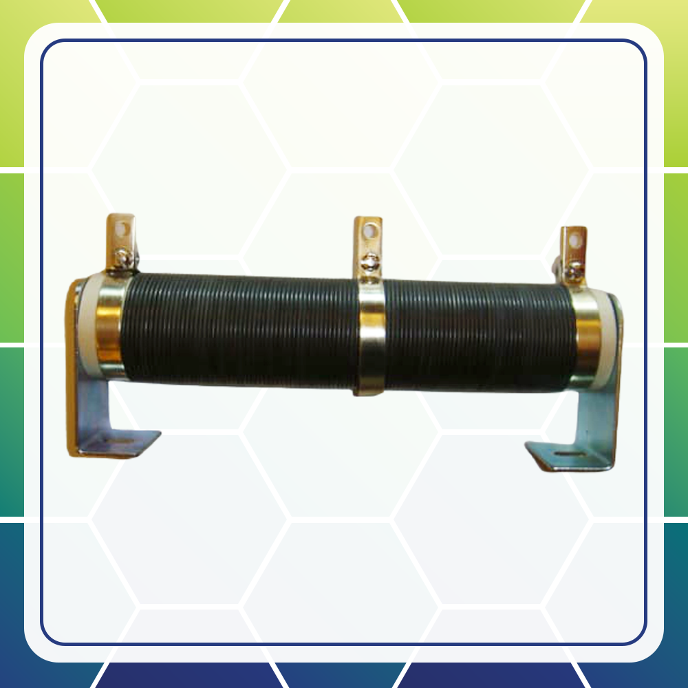
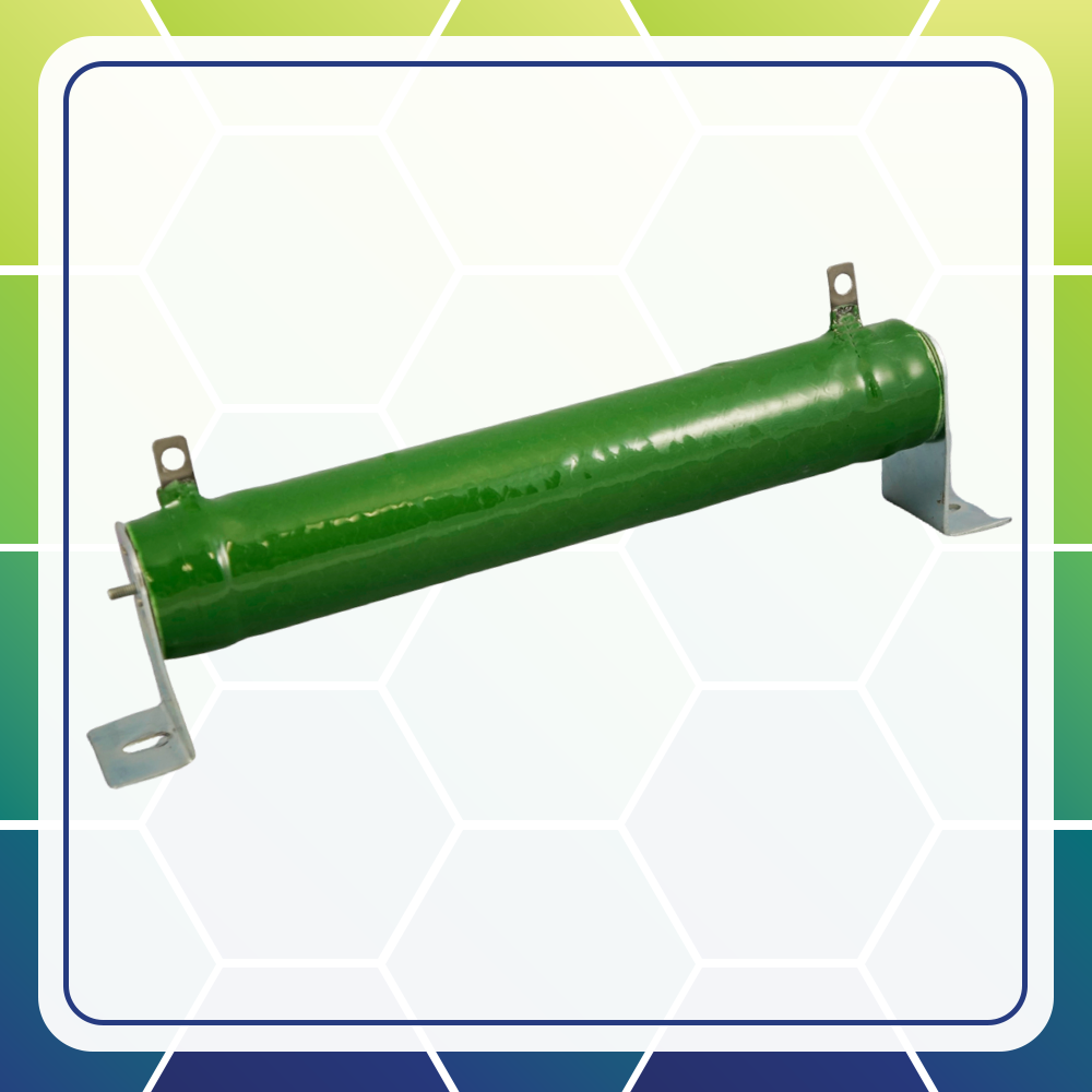
- Wire-Wound Resistors: Renowned for their durability and high-power handling capabilities, these resistors are a trusted choice for many load applications. Their precision and reliability make them ideal for the demanding requirements of load testing.
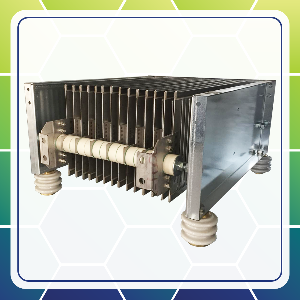
- Grid Resistors: Ideal for high power and current applications, grid resistors are robust and designed to stand up to industrial challenges, ensuring your infrastructure is impeccably prepared for full deployment.
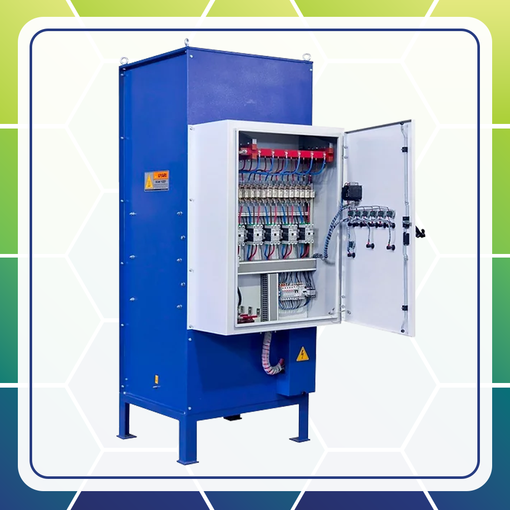
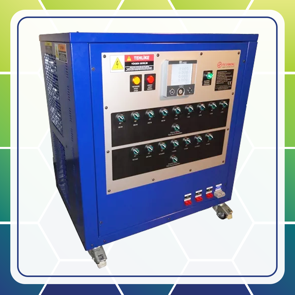
- Load Bank Resistors: Designed specifically for load testing, our load bank resistors can be both portable and stationary, providing flexibility and efficiency in testing scenarios.
Why Choose Hill Tech?
At Hill Tech, we are committed to providing resistor solutions that empower your server farm with unmatched reliability and efficiency. Our high-performance products are supported by our exceptional service, ensuring you have everything you need to optimize your infrastructure before it goes live.
Interested in learning more about how our resistors can benefit your operations? Our team of experts is here to help tailor a solution that fits your specific needs. We invite you to contact us for further discussions, detailed product information, or to request a quote.
Contact us today and let us help power your success with our world-class resistor solutions. Together, we’ll build a future-ready server farm that stands the test of time. Please visit our website and submit a quote at https://hill-tech.com/, or contact us at 847-255-4400, fax us at (847) 255-0192, or email us at sales@hilltech.com. And be sure to look at our social media pages, linked below!
Hill Technical Sales provides expert design and implementation of quality components for Electrical Power Conversion & Distribution, Thermal Management, UV Curing, and High-Speed Industrial Imaging for more information:
Connect with us: ![]()
![]()
![]()
![]()