ARLINGTON HEIGHTS, ILLINOIS, USA, Monday, June 24, 2013: Hill Tech Sales, a leader in Components for Electrical Power Conversion today posted information on using true Full-range fuses to reduce the size of switchgear.
In the past, Full-range fuses used an inappropriate element design where they “age” prematurely because they operate in the fast overcurrent range. This ageing is the changing element’s characteristics because of the increased power loss during operation.
Correctly designed Full-range fuses will interrupt any value of current from short-circuit to overload interruption. They have all the characteristics of back-up fuses plus the further ability for protection in the overload range. Distribution transformer circuits should use Full-range fuses where there may not be protection on the secondary side of the transformer, and the primary fuse is needed to clear a secondary system fault.
Full-Range fuse other construction concept

Typical construction for Back-up & General Purpose fuses
Our Full-range fuses are designed using a two zone design concept; each zone has a different element design which lowers power losses and temperature rise leading to reliable operation in the overload range.
Full-Range fuse NEW concept

Other Full-range fuse do not use a dual zone construction
New design concept for Full-range fuses:
Two Zone concept, back-up zone, overload zone (Thermal Zone)
Special melting element material for parallel melting element design
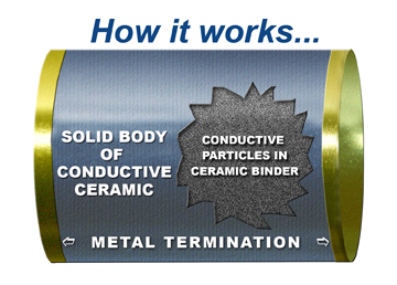
Back-up zone
Back-up zone consists of upto 15 individual silver melting elements wound onto a star-shaped carrier imbedded in quartz sand.
Overload zone (Thermal Zone)
The elements in this zone are notched, which reduces the element cross section generating power loss and creating heat. In order to minimize the effects of this heat, two things are done. First, the heat is confined to a thermal separated from other parts of the fuse by a thermal barrier. Secondly, the melting elements are made of a special alloy differentiating it from silver (melting point 960°C) which is typically used.

Full-range fuse dual zone method
Melting element materials has three important properties:
- Low melting point ~ 600°C.
- Enhanced heat absorption by the decay of metal-oxide components in the arcing process. Metal oxides are created by internal oxidation of the alloy just before reaching the melting temperature.
- Increased recovery voltage. The AC voltage arc is immediately absorbed after current zero making re-ignition very high. These fault arcs are extinguished much faster when made of this alloy as compared to elements of pure silver.
The two zones are placed in series for good short-circuit and overload protection.
Full-range fuses protect like two fuses, Back-up & General-Purpose.

Why Full-Range fuse is better than Back-up or GP
Full-range fuses protect the transformer by:
- Meeting transformer inrush current points.
- Have a rated current sufficiently above the transformer rated current in order to allow for admissible overloads.
- Provide best possible protection during overload caused by winding short circuits.
- Discriminative currents over the complete interrupting range.
Increasing Switchgear safety
Switchgear safety can be increased by using Full-range fuses on the high voltage side of the transformer because other methods only protect against:
- Non coordinated fuses on the low voltage side of the transformer
- Short circuits in the transformer winding, ie transformer insulation failures
- Earth faults in the area around the transformer bushings
The danger of this method is that admissible peak transformer currents are exceeded when the cables are loaded with their maximum, and transformer life-reducing excessive loads are only noticed after years.
Also, back-up fuses used on the primary side of the transformer do not protect in an overload range situation where the insulation is in the process of failing. A slow steady current rise can occur when cracking insulation causes more and more windings to short-circuit. This increase in current occurs in the small overcurrent range of the transformer.
Full-range fuses will effectively protect transformers against overloads caused either by the load or winding short-circuit. These fuses can be used as redundant protection so that even after failure of all other protective devices on the high and low voltage side, it offers a last means of safety before catastrophic damage occurs to your installation, buildings and environment.
Consider Full-range fuses for applications with long cable runs and/or high transformer impedance and Switchgear without 3-phase disconnecting device.
Reduced size and cost of switchgear by Full-range fuse
Back-up fuses need to be de-rated in transformer applications. For a 100A application a 125A back-up fuse would typically be used. With Full-range fuses, there is no de-rating of the fuse value, so a 100A is appropriate for a 100A application.
Protecting distribution transformers with full-range fuses

Schematic showing HV Full-range fuse location in order to protection transformer
Ratings available:
- 6/12 kV: 6.3 A – 100 A
- 10/24 kV: (6.3 A) – 50 A
Applications:
- Power centers
- Power transformer protection
- Load interrupters
- Feeder circuit protection
- Mine rectifiers
For more questions on this article contact:
Andrew Hill
Hill Technical Sales
216 West Campus Drive
Arlington Heights, IL 60004
Tel: +1- 847-255-4400 ext 12 Fax: +1-847-255-0192
You may also visit: http://www.hilltech.com/